We are creating a simple system that can switch a relay from everywhere, based on a WEMOS D1 mini and a relay shield.
With cloud integration the switch of the relay controlled by the IoT Guru Cloud library, where we will use a simple HTML & JavaScript page with two buttons.
Supplies
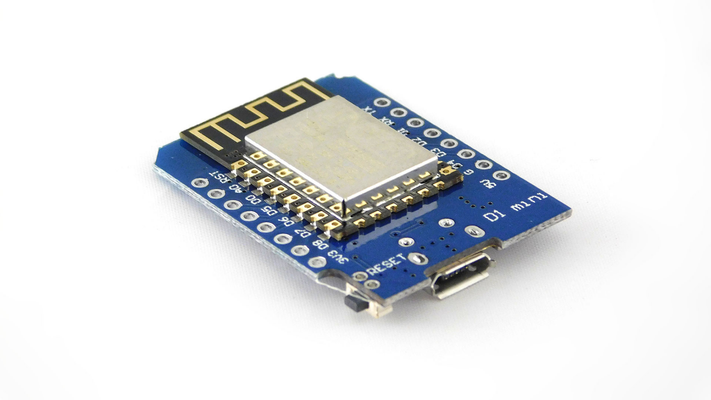
WEMOS D1 mini or any other ESP based MCU
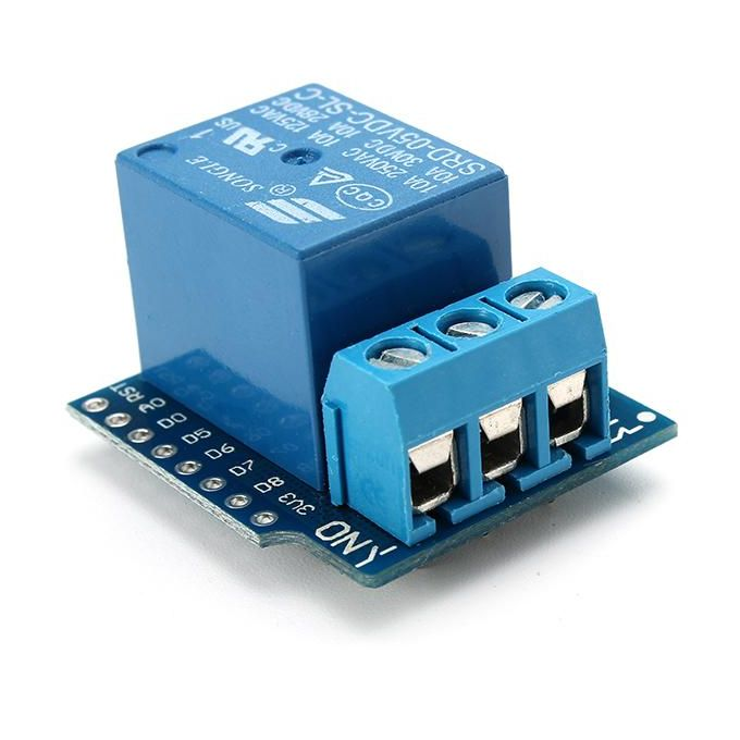
WEMOS relay shield or relay
Step 1
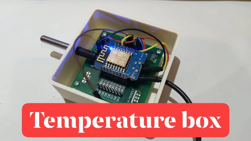
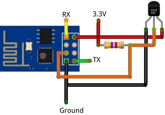
Solder and stack the WEMOS D1 mini and the relay shield together like this:
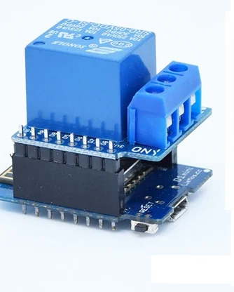
Alternatively you can use any ESP based MCU and relay.
Step 2
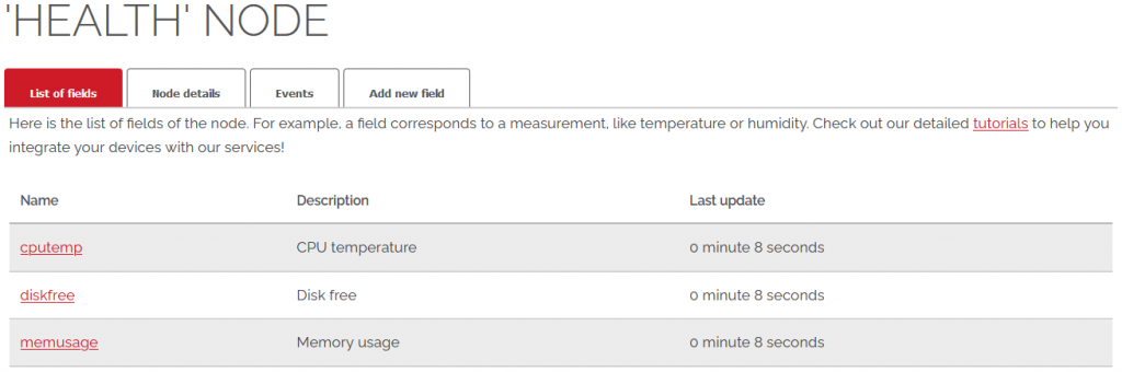
If you don’t have already, you need to create a device, a node and a field in our cloud, follow this articles:
- Tutorials – Devices (suggested name:
WEMOS D1 mini) - Tutorials – Nodes (suggested name:
Relay node) - Tutorials – Fields (suggested name:
relay)
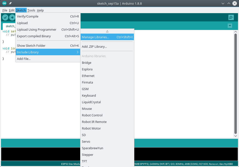
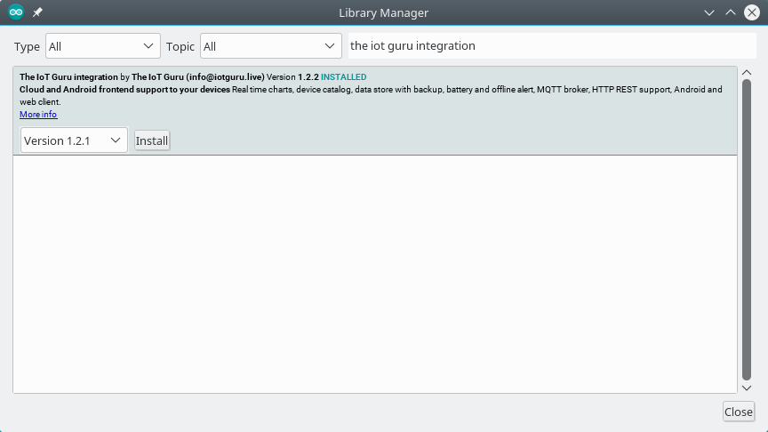
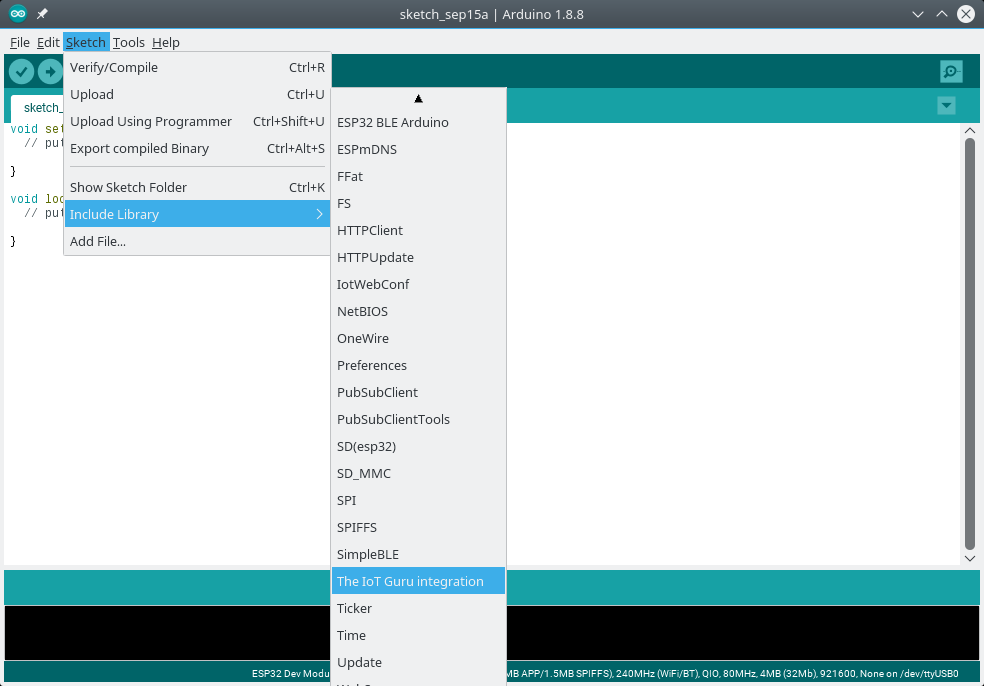
If you haven’t installed it yet, install our official Arduino library:
Step 3
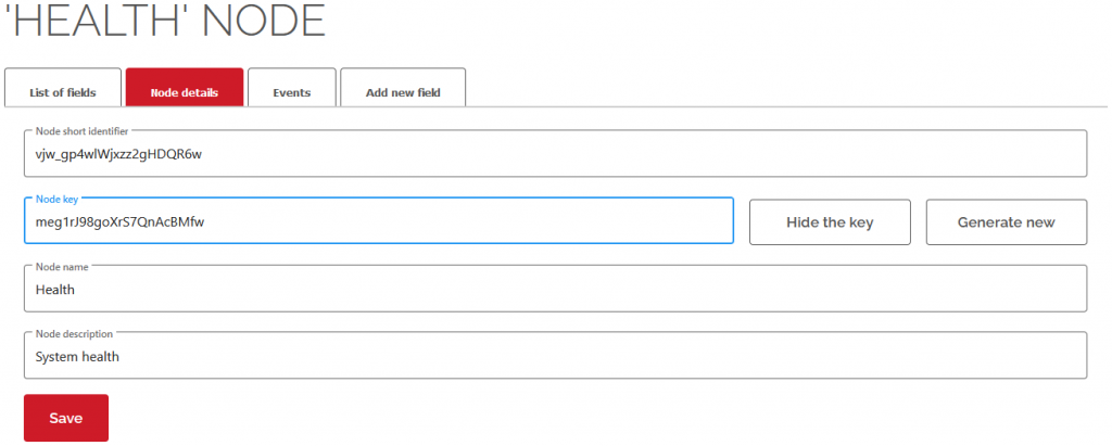
To connect with our cloud, you need to gather six identifier:
- userShortId: the short identifier of you
- deviceShortId: the short identifier of your device
- deviceKey: the secret key of your device
- nodeShortId: the short identifier of your node
- nodeKey: the secret key of your node
- fieldName: the name of the field
Step 4
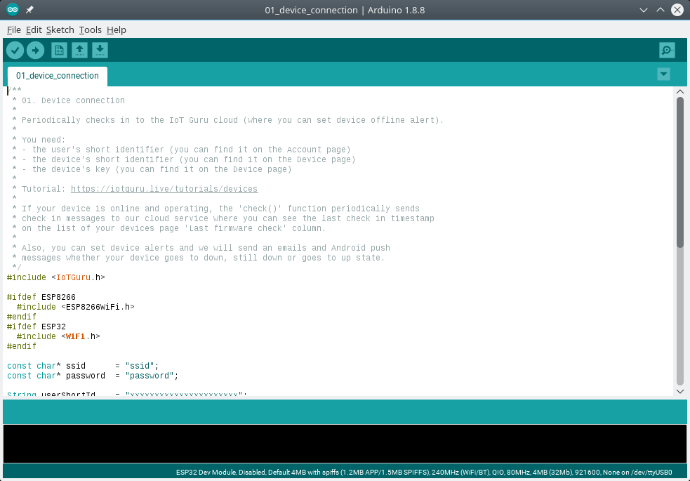
Create a new Arduino sketch, copy-paste the following code and replace the ssid, the password, the userShortId, the deviceShortId, the deviceKey , the nodeShortId and the fieldName with your Wifi credentials and with your gathered values:
#include <IoTGuru.h>

#ifdef ESP8266
  #include <ESP8266WiFi.h>
#endif
#ifdef ESP32
  #include <WiFi.h>
#endif

#define RELAY_PIN         5

/**
 * WiFi parameters.
 */
const char* ssid        = "ssid";
const char* password    = "password";
WiFiClient client;

/**
 * Initialize the connection with the cloud.
 */
String userShortId      = "xxxxxxxxxxxxxxxxxxxxxx";
String deviceShortId    = "yyyyyyyyyyyyyyyyyyyyyy";
String deviceKey        = "zzzzzzzzzzzzzzzzzzzzzz";
IoTGuru iotGuru         = IoTGuru(userShortId, deviceShortId, deviceKey);

/**
 * Constants of the MQTT channel check.
 */
String nodeShortId      = "nnnnnnnnnnnnnnnnnnnnnn";
String fieldName        = "relay";

void setup() {
    Serial.begin(115200);
    delay(10);

    WiFi.begin(ssid, password);
    while (WiFi.status() != WL_CONNECTED) {
        delay(50);
        Serial.print(".");
    }
    Serial.println("");

    /**
     * Set the relay pin.
     */
    pinMode(RELAY_PIN, OUTPUT);

    iotGuru.setCallback(&callback);
    iotGuru.setDebugPrinter(&Serial);
    iotGuru.setNetworkClient(&client);
}

void loop() {
    iotGuru.loop();
    delay(10);
}

void callback(const char* cbNodeShortId, const char* cbFieldName, const char* message) {
    Serial.print(cbNodeShortId);Serial.print(" - ");Serial.print(cbFieldName);Serial.print(": ");Serial.println(message);

    if (strcmp(cbNodeShortId, nodeShortId.c_str()) == 0) {
        if (strcmp(cbFieldName, fieldName.c_str()) == 0) {
            if (strcmp(message, "0") == 0) {
                Serial.println("Switch relay to LOW");
                digitalWrite(RELAY_PIN, LOW);
            } else {
                Serial.println("Switch relay to HIGH");
                digitalWrite(RELAY_PIN, HIGH);
            }
        }
    }
}
Step 5
Plug your WEMOS D1 mini to your computer with an USB cable, compile the code you’ve edited above and upload it to your WEMOS D1 mini. Check the Serial console about the connection messages.
Step 6
Create a HTML page on your computer or your webserver and copy-paste the following snippet into the body tag; replace the nnn..nnn with your nodeKey value:
<center>
  <button id="mqttOn" name="mqttOn" value="ON">ON</button>
  <button id="mqttOff" name="mqttOff" value="OFF">OFF</button>
  <hr/>
</center>

<script src="https://cdnjs.cloudflare.com/ajax/libs/jquery/3.4.1/jquery.min.js"></script>

<script>
    $("#mqttOn").click(function(){
        $.ajax({url: "https://api.iotguru.live/mqtt/send/nnnnnnnnnnnnnnnnnnnnnn/relay/1"});
    });
    $("#mqttOff").click(function(){
        $.ajax({url: "https://api.iotguru.live/mqtt/send/nnnnnnnnnnnnnnnnnnnnnn/relay/0"});
    });
</script>
If you have reached this point, pressing the ON and OFF buttons will turn the relay on and off.