Categories
Tutorial

Remote relay switch

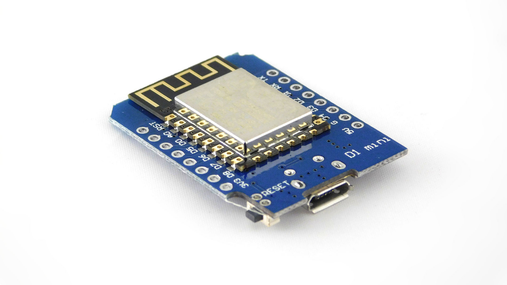
We are creating a simple system that can switch a relay from everywhere, based on a WEMOS D1 mini and a relay shield.

With cloud integration the switch of the relay controlled by the IoT Guru Cloud library, where we will use a simple HTML & JavaScript page with two buttons.

Supplies

WEMOS D1 mini or any other ESP based MCU
WEMOS relay shield or relay

Step 1

Solder and stack the WEMOS D1 mini and the relay shield together like this:

Alternatively you can use any ESP based MCU and relay.

Step 2

If you don’t have already, you need to create a device, a node and a field in our cloud, follow this articles:

If you haven’t installed it yet, install our official Arduino library:

Step 3

To connect with our cloud, you need to gather six identifier:

  • userShortId: the short identifier of you
  • deviceShortId: the short identifier of your device
  • deviceKey: the secret key of your device
  • nodeShortId: the short identifier of your node
  • nodeKey: the secret key of your node
  • fieldName: the name of the field

Step 4

Create a new Arduino sketch, copy-paste the following code and replace the ssid, the password, the userShortId, the deviceShortId, the deviceKey , the nodeShortId and the fieldName with your Wifi credentials and with your gathered values:

#include <IoTGuru.h>

#ifdef ESP8266
  #include <ESP8266WiFi.h>
#endif
#ifdef ESP32
  #include <WiFi.h>
#endif

#define RELAY_PIN         5

/**
 * WiFi parameters.
 */
const char* ssid        = "ssid";
const char* password    = "password";
WiFiClient client;

/**
 * Initialize the connection with the cloud.
 */
String userShortId      = "xxxxxxxxxxxxxxxxxxxxxx";
String deviceShortId    = "yyyyyyyyyyyyyyyyyyyyyy";
String deviceKey        = "zzzzzzzzzzzzzzzzzzzzzz";
IoTGuru iotGuru         = IoTGuru(userShortId, deviceShortId, deviceKey);

/**
 * Constants of the MQTT channel check.
 */
String nodeShortId      = "nnnnnnnnnnnnnnnnnnnnnn";
String fieldName        = "relay";

void setup() {
    Serial.begin(115200);
    delay(10);

    WiFi.begin(ssid, password);
    while (WiFi.status() != WL_CONNECTED) {
        delay(50);
        Serial.print(".");
    }
    Serial.println("");

    /**
     * Set the relay pin.
     */
    pinMode(RELAY_PIN, OUTPUT);

    iotGuru.setCallback(&callback);
    iotGuru.setDebugPrinter(&Serial);
    iotGuru.setNetworkClient(&client);
}

void loop() {
    iotGuru.loop();
    delay(10);
}

void callback(const char* cbNodeShortId, const char* cbFieldName, const char* message) {
    Serial.print(cbNodeShortId);Serial.print(" - ");Serial.print(cbFieldName);Serial.print(": ");Serial.println(message);

    if (strcmp(cbNodeShortId, nodeShortId.c_str()) == 0) {
        if (strcmp(cbFieldName, fieldName.c_str()) == 0) {
            if (strcmp(message, "0") == 0) {
                Serial.println("Switch relay to LOW");
                digitalWrite(RELAY_PIN, LOW);
            } else {
                Serial.println("Switch relay to HIGH");
                digitalWrite(RELAY_PIN, HIGH);
            }
        }
    }
}

Step 5

Plug your WEMOS D1 mini to your computer with an USB cable, compile the code you’ve edited above and upload it to your WEMOS D1 mini. Check the Serial console about the connection messages.

Step 6

Create a HTML page on your computer or your webserver and copy-paste the following snippet into the body tag; replace the nnn..nnn with your nodeKey value:

<center>
  <button id="mqttOn" name="mqttOn" value="ON">ON</button>
  <button id="mqttOff" name="mqttOff" value="OFF">OFF</button>
  <hr/>
</center>

<script src="https://cdnjs.cloudflare.com/ajax/libs/jquery/3.4.1/jquery.min.js"></script>

<script>
    $("#mqttOn").click(function(){
        $.ajax({url: "https://api.iotguru.live/mqtt/send/nnnnnnnnnnnnnnnnnnnnnn/relay/1"});
    });
    $("#mqttOff").click(function(){
        $.ajax({url: "https://api.iotguru.live/mqtt/send/nnnnnnnnnnnnnnnnnnnnnn/relay/0"});
    });
</script>

If you have reached this point, pressing the ON and OFF buttons will turn the relay on and off.

Categories
Example Tutorial

OTA firmware update

Simple and easy Over-The-Air firmware update for any ESP8266/ESP32 MCU with cloud storage? This is it! 🙂

Step 1

If you don’t have already a device, you need to create a device in our cloud, follow this article: tutorials/devices

Install our official Arduino library: ArduinoIDE integration

Step 2

To connect with the cloud, you need to gather three identifier:

  • userShortId: the short identifier of you
  • deviceShortId: the short identifier of your device
  • deviceKey: the secret key of your device

Step 3

Create a new Arduino sketch, copy-paste the following code and replace the ssid, the password, the userShortId, the deviceShortId and the deviceKey with your Wifi credentials and your device’s values:

#include <IoTGuru.h>

#ifdef ESP8266
  #include <ESP8266WiFi.h>
#endif
#ifdef ESP32
  #include <WiFi.h>
#endif

const char* ssid        = "ssid";
const char* password    = "password";

const char* ota_version = "example-1.0.0";

String userShortId      = "xxxxxxxxxxxxxxxxxxxxxx";
String deviceShortId    = "yyyyyyyyyyyyyyyyyyyyyy";
String deviceKey        = "zzzzzzzzzzzzzzzzzzzzzz";
IoTGuru iotGuru         = IoTGuru(userShortId, deviceShortId, deviceKey);

WiFiClient client;

void setup() {
    Serial.begin(115200);
    delay(10);

    WiFi.begin(ssid, password);
    while (WiFi.status() != WL_CONNECTED) {
        delay(50);
        Serial.print(".");
    }
    Serial.println("");

    iotGuru.setCheckDuration(60000);
    iotGuru.setDebugPrinter(&Serial);
    iotGuru.setNetworkClient(&client);

    iotGuru.firmwareUpdate(ota_version);
}

void loop() {
    if (iotGuru.check(ota_version)) {
        ESP.restart();
    }
}

Step 4

Compile the sketch and put it to the device with the old common way., the first firmware installation is inevitable. Also, you need to find the compiled firmware binary, but it is an easy task:

  1. Sketch - Export compiled Binary (Ctrl-Alt-S)
  2. Sketch - Show Sketch Folder (Ctrl-K)

Step 5

Upload the firmware binary to your Firmware storage:

Step 6

Set the Device firmware version field of your device:

Step 7

Your device will periodically check to see if its own version and the set version match; if so, then nothing will happen. If the two versions are different, it will reboot and update itself to what you specified in the Device firmware version field.

6288: {check(ota_version):72} - ENTRY
6292: {check(ota_version):75} - Send request to the cloud: http://api.iotguru.live/firmware/check/xxxxxxxxxxxxxxxxxxxxxx/example-1.0.0
6402: {check(ota_version):84} - Response received from the cloud (status code 304)
6402: {check(ota_version):86} - EXIT

Categories
Tutorial

Soil moisture sensor

We are creating a device that measures soil moisture, based on a WEMOS D1 mini and a Capacitive Soil Moisture sensor.

With cloud integration the measurement of the sensor sent to the IoT Guru Cloud, where we get fancy graphs and we can set a warning that we need to watering the plant.

Supplies:

  • WEMOS D1 mini
  • Capacitive Soil Moisture sensor

Step 1

The Capacivite Soil Moisture sensor has three pin:

  1. Ground
  2. Vcc
  3. Analog output

You can connect this pins to the WEMOS D1 mini in same order:

  1. D5
  2. D0
  3. A0

Step 2

The source code is contains an IoT Guru Cloud integration, you can check out our Tutorials about the integration. You will need:

  • userShortId
  • deviceShortId
  • deviceKey
  • nodeShortId
  • fieldName

Step 3

The code will send an analogue measurement in every one minute. Compile it and upload the firmware to your WEMOS D1 mini.

#include <IoTGuru.h>

#include <ESP8266WiFi.h>

const char* ssid      = "ssid";
const char* password  = "password";

WiFiClient client;

String userShortId    = "uuuuuuuuuuuuuuuuuuuuuu";
String deviceShortId  = "dddddddddddddddddddddd";
String deviceKey      = "kkkkkkkkkkkkkkkkkkkkkk";
IoTGuru iotGuru = IoTGuru(userShortId, deviceShortId, deviceKey);

String nodeShortId    = "nnnnnnnnnnnnnnnnnnnnnn";
String fieldName      = "analog";

void setup() {
    Serial.begin(115200);
    delay(10);

    WiFi.begin(ssid, password);
    while (WiFi.status() != WL_CONNECTED) {
        delay(50);
        Serial.print(".");
    }
    Serial.println("");

    /**
     * Set the callback function.
     */
    iotGuru.setCallback(&callback);
    /**
     * Set the debug printer (optional).
     */
    iotGuru.setDebugPrinter(&Serial);
    /**
     * Set the network client.
     */
    iotGuru.setNetworkClient(&client);

    pinMode(14, OUTPUT);
    pinMode(16, OUTPUT);
    digitalWrite(14, LOW);
    digitalWrite(16, HIGH);
}

volatile unsigned long nextSendUptime = 0;

void loop() {
    iotGuru.loop();

    if (nextSendUptime < millis()) {
        nextSendUptime = millis() + 60000;
        int analogValue = analogRead(A0);
        float analog = analogValue * (3.2 / 1023.0f) * 100.0f;
        Serial.println("Analog value: " + String(analog));
        iotGuru.sendMqttValue(nodeShortId, fieldName, analog);
    }
}

void callback(const char* nodeShortId, const char* fieldName, const char* message) {
    Serial.print(nodeShortId);Serial.print(" - ");Serial.print(fieldName);Serial.print(": ");Serial.println(message);
}

Step 4

Check the chart of the measurements:

Categories
Tutorial

Temperature Sensor Box

Simple DS18B20 based temperature sensor appliance with open source 3D printable box and prototype PCB.

The box and the prototype PCB is optional, only one ESP8266 based MCU is needed and one DS18B20 temperature sensor. I suggest to you a WEMOS D1 mini, but this example works with an ESP-01 as well.

This example does not explain how to write and upload an Arduino program to the ESP8266 MCU, so be aware of this skill before following me. 🙂

Supplies

  1. ESP8266 MCU (recommended WEMOS D1 mini)
  2. DS18B20
  3. 4.7 kΩ resistor
  4. some wire
  5. optionally prototype PCB for WEMOS D1 mini
  6. optionally 3D printed box

Step 1

It’s easy as pie, check the wiring schematics on the picture:

  • In case of bare ESP8266 board, connect the RX and TX to your USB-serial device, in case of any board with integrated USB this is not necessary.
  • Connect the GND and VCC to the ESP8266 board and to the DS18B20 sensor.
  • Connect the resistor between the VCC and the data wire of the DS18B20 sensor.
  • Connect the data wire of the DS18B20 sensor to one GPIO of the MCU (for example GPIO 2).

Step 2

You need three additional library:
– OneWire: one-wire
– DallasTemperature: dallas-temperature
– The IoT Guru Integration: the-iot-guru-integration

Step 3

The IoT Guru cloud is a free cloud backend, you can use it to save and show measurements really easy. You need to create a device, a node and a field:

To connect with the cloud, you need to gather five identifier:

  • userShortId: the short identifier of you
  • deviceShortId: the short identifier of your device
  • deviceKey: the secret key of your device
  • nodeShortId: the short identifier of your device
  • fieldName: the name of the field

Step 4

Here is the example code, you need to replace the identifiers to your identifier, replace the SSID and the password to your WiFi credentials and check the GPIO number of the DS18B20 data wire.

#include <OneWire.h>
#include <DallasTemperature.h>

#include <IoTGuru.h>
#include <ESP8266WiFi.h>

const char* ssid      = "iotguru.cloud";
const char* password  = "********";

String userShortId    = "l4jLDUDDVKNNzx4wt2UR6Q";
String deviceShortId  = "uAjbSzf8LvlrofvwYU8R6g";
String deviceKey      = "hacfIjPn6KbBf2md8nxNeg";
IoTGuru iotGuru = IoTGuru(userShortId, deviceShortId, deviceKey);

String nodeKey        = "tGib1WSRvEGJ98rQYU8R6g";
String fieldName      = "temperature";

#define ONE_WIRE_BUS 2
OneWire oneWire(ONE_WIRE_BUS);
DallasTemperature sensors(&oneWire);

void setup(void)
{
    Serial.begin(115200);
    delay(10);

    WiFi.begin(ssid, password);
    while (WiFi.status() != WL_CONNECTED) {
        delay(50);
        Serial.print(".");
    }
    Serial.println("");

    iotGuru.setCheckDuration(60000);
    iotGuru.setDebugPrinter(&Serial);

    sensors.begin();
}

void loop(void)
{
    iotGuru.check();
    sensors.requestTemperatures();

    float measuredValue = sensors.getTempCByIndex(0);
    Serial.println("The first sensor temperature: " + String(measuredValue) + " °C");
  
    iotGuru.sendHttpValue(nodeKey, fieldName, measuredValue);

    delay(30000);      
}

Step 5

Upload the compiled firmware to your device. If everything is fine, your thermometer box will send the sensor measurements to the cloud and you’ll see such nice graphs over time if enough measurements have accumulated.

More information and examples:

Categories
Tutorial

ArduinoIDE integration

Step 1

To install The IoT Guru integration into your Arduino IDE you can use the Library Manager (available from IDE version 1.6.2). Open the IDE and click to the Sketch menu and then Include Library > Manage Libraries.

Step 2

Then the Library Manager will open and you will find a list of libraries that are already installed or ready for installation. In order to install The IoT Guru integration, search for “The IoT Guru integration“, scroll the list to find it and click on it.

Finally click on install and wait for the IDE to install The IoT Guru integration. Downloading may take time depending on your connection speed. Once it has finished, an Installed tag should appear next to the The IoT Guru integration library. You can close the Library Manager.

Step 3

You can now find The IoT Guru integration available in the Sketch > Include Library menu.

Step 4

We included some examples to our library, so that you can choose various examples to integrate your devices with our services, for example the basic device connection:

That’s all, folks! 🙂

Categories
Hardware Tutorial

Raspberry Pi health monitoring

This tutorial will show you how to use IoT Guru Cloud to monitor the health of your Raspberry Pi and alert you when something is wrong.

At the end of this tutorial, you will run a Python script every five minutes using crontab to send your Raspberry Pi’s temperature, free disk space and memory usage to the cloud using our REST API.

Step 1

First of all, we suggest to read our basic tutorials about devices, nodes and fields:

Step 2

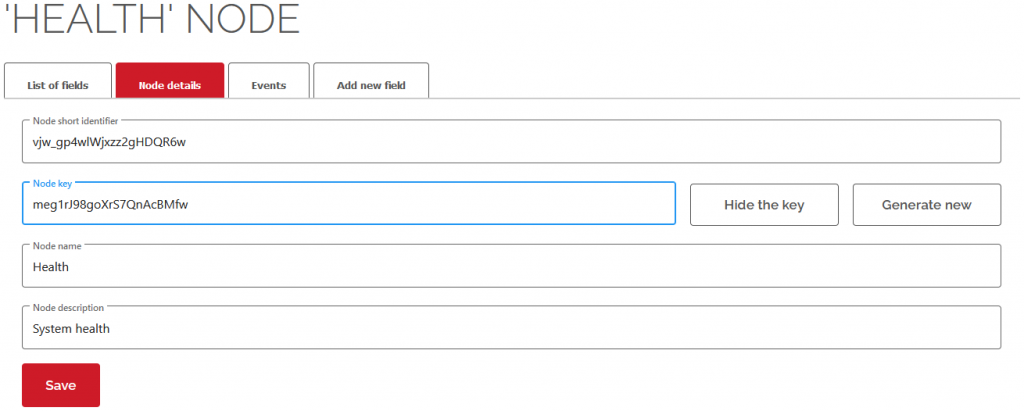
Create a device of your Raspberry Pi, create a node of this device, and name it as ‘Health’, and create three fields like this:

Step 3

Copy the node key of the ‘Health’ node (by click ‘Show the key’ button).

Step 4

Create a raspi_health.py file with your favorite editor and copy-paste this code below. Don’t forget to replace the nodeKey value with your node key!

import os
import ssl
import re
import subprocess
import urllib.request

# Replace with your nodeKey:
nodeKey = 'meg1rJ98goXrS7QnAcBMfw'

# DO NOT EDIT BELOW, unless you trust yourself

cpu_temp_endpoint  = 'https://api.iotguru.cloud/measurement/create/' + nodeKey + '/cputemp/'
disk_free_endpoint = 'https://api.iotguru.cloud/measurement/create/' + nodeKey + '/diskfree/'
mem_usage_endpoint = 'https://api.iotguru.cloud/measurement/create/' + nodeKey + '/memusage/'

#!/usr/bin/env python3

def getRAMinfo():
    p = os.popen('free')
    i = 0
    while 1:
        i = i + 1
        line = p.readline()
        if i==2:
            RAM_stats = line.split()[1:4]
            RAM_total = int(RAM_stats[0])
            RAM_free = int(RAM_stats[2])
            RAM_freeperc = int(RAM_free / RAM_total * 100)
            return RAM_freeperc

def postData(endpoint, value):
    gcontext = ssl.SSLContext()
    url = endpoint + str(value)
    req = urllib.request.Request(url)
    resp = urllib.request.urlopen(req, context=gcontext)
    respData = resp.read()
    print(respData)

cputemp = subprocess.Popen('cat /sys/class/thermal/thermal_zone0/temp', shell=True, stdout=subprocess.PIPE).stdout.read().decode('utf-8')
cputemp = int(int(cputemp) / 1000)
postData(cpu_temp_endpoint, cputemp)

usedspace = subprocess.Popen('df --output=pcent / | awk -F\'%\' \'NR==2{print $1}\'', shell=True, stdout=subprocess.PIPE).stdout.read().decode('utf-8')
freespace = 100 - int(usedspace)
postData(disk_free_endpoint, freespace)

freeram = getRAMinfo()
postData(mem_usage_endpoint, freeram)

Step 5

Test the script in the command line, you will get something like this:

> python3 raspi_health.py
b'{"epoch":18567,"nodeId":"f1cf3da0-1c34-11eb-be3c-3f829e309568","nodeShortId":"vjw_gp4wlWjxzz2gHDQR6w","field":"cputemp","created":"4eb38920-1c37-11eb-be3c-3f829e309568","floatValue":32.0,"textValue":null}'
b'{"epoch":18567,"nodeId":"f1cf3da0-1c34-11eb-be3c-3f829e309568","nodeShortId":"vjw_gp4wlWjxzz2gHDQR6w","field":"diskfree","created":"4ed9d5d0-1c37-11eb-b075-c16b57e52174","floatValue":16.0,"textValue":null}'
b'{"epoch":18567,"nodeId":"f1cf3da0-1c34-11eb-be3c-3f829e309568","nodeShortId":"vjw_gp4wlWjxzz2gHDQR6w","field":"memusage","created":"4f113980-1c37-11eb-be3c-3f829e309568","floatValue":44.0,"textValue":null}'

Step 6

Add the script to the end of your crontab, by using the crontab -e command:

*/5 * * * * python3 /home/pi/raspi_health.py > /dev/null 2>&1

Step 7

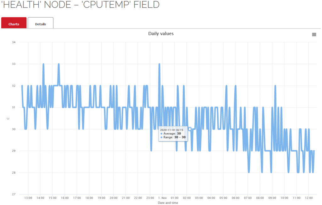
Check out the chart of one of your field:

That’s all, folks, enjoy your charts of your Raspberry Pi. 🙂

Based on Jasonb’s forum post: tutorial-monitor-health-of-your-raspberry-pi

Thank you, Jason! 🙂

Categories
Example

Complex chart example

Display daily, weekly, monthly and yearly charts of the (in source) specified nodes and fields with auto-refresh feature on your website.

HTML source

https://github.com/IoTGuruLive/web-api-examples/blob/master/complex-chart.html

Live demo

https://iotgurulive.github.io/web-api-examples/complex-chart.html

Categories
Prototypes

Dust box

Inside the 3D printed top enclosure is a WEMOS D1 Mini board, sitting on our custom prototype PCB. This board gives you some easy expandability to add your own sensors and hardware.

The Dust Box is using the SDS011 laser particle sensor to determine what’s in the air and the BME680 or BME280 sensor for general environmental monitoring (and VOC monitoring in case of BME680).

Just snap together the two half and plug it into a convenient USB power source, and it will be does its job… 🙂

GitHub project with plans, images, files, sources and issues:
https://github.com/IoTGuruLive/dust_box

https://iotguru.cloud/node/pGG1Q1HEfK76tqKA-xwR6Q

Happy forking and modding, it is open source! 🙂