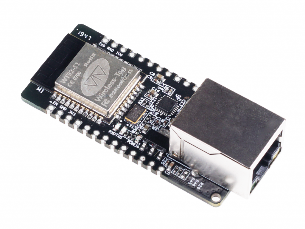
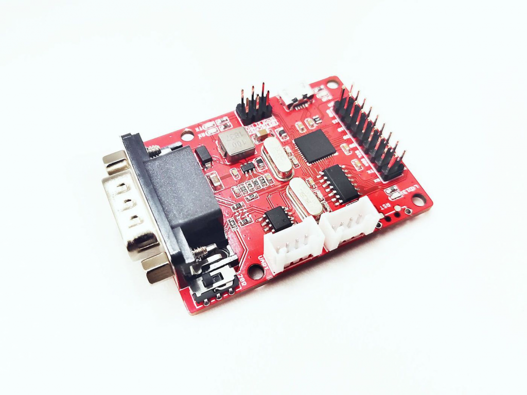
WT32-ETH01 is an embedded serial to Ethernet module based on the ESP32 series WT32-S1 MCU. The module integrates an optimized TCP/IP protocol stack, which is convenient for users to easily complete the networking functions of embedded devices while reducing development time cost. In addition, the module is compatible with half-pad and through-hole connectors. The board width is a universal width and therefore, it can be directly soldered to boards, connectors, or even breadboards, which is convenient for users to use in different scenarios.
Support complete TCP/IP protocol stack
Rich wireless communication interface
Multiple working modes using through holes and half-pads
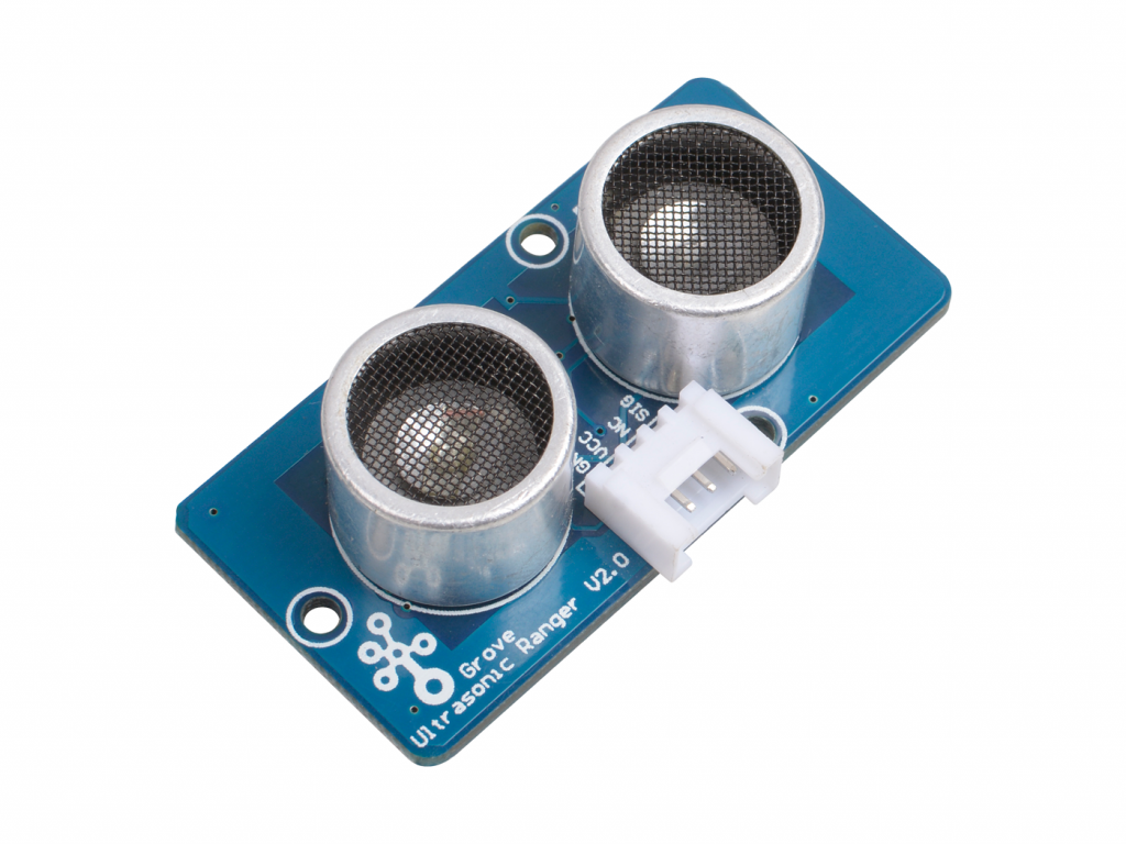
The Grove – Ultrasonic Distance Sensor is an ultrasonic transducer that utilizes ultrasonic waves to measures distance. It can measure from 3cm to 350cm with the accuracy up to 2mm.
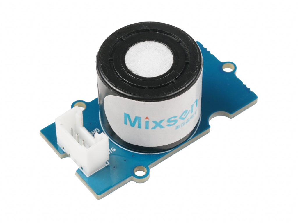
Grove – Oxygen Sensor (MIX8410) is an electrochemical oxygen sensor and it can be used to test the oxygen concentration in air. Under the catalysis of the electrodes, a redox reaction occurs on the working electrode and the counter electrode, thereby generating a current. The concentration of oxygen in the air is calculated by measuring this current and referring to the oxygen concentration linear characteristic graph.
High sensitivity (0.1±0.03 mA) with linear output
High stability with <10s response time
Environmental protection design
Advanced anti-leakage technology which greatly reduces the probability of leakage
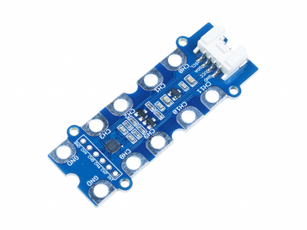
The Grove – 12 Key Capacitive I2C Touch Sensor V3 (MPR121) is a multi-channel proximity capacitive touch sensor. It’s a 3-in-1 module with the following features: Capacitance Sensing. Tough Sensing.
Internal 10-bit ADC
Integrated independent autocalibration for each electrode input
Completely independent electrodes with built-in autoconfiguration
I2C interface, with IRQ, Interrupt output to advise electrode status changes
Hardware configurable I2C address
12 electrodes/capacitance sensing inputs in which 8 are multifunctional for LED driving and GPIO
Autoconfiguration of charge current and charge time for each electrode input
Separate touch and release trip thresholds for each electrode, providing hysteresis and electrode independence
Add two more GND pin and expand the gap of pins for safe handling
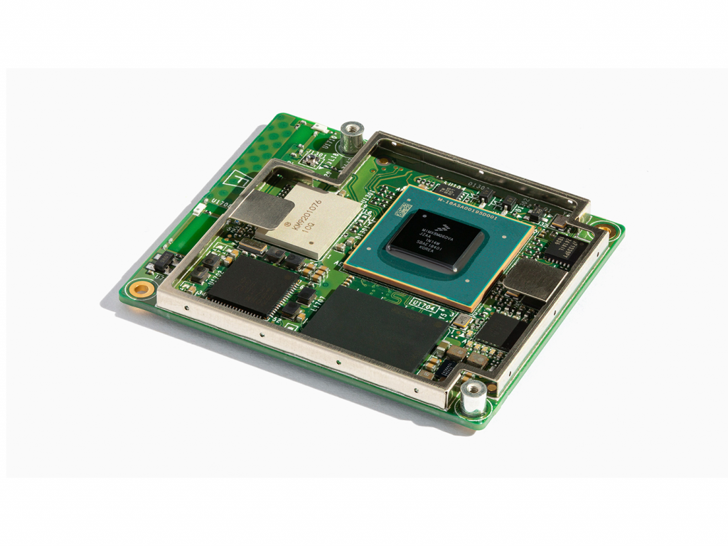
The Coral System-on-Module (SoM) is a fully-integrated system that helps you build embedded devices that demand fast machine learning (ML) inferencing. It contains NXP’s iMX 8M system-on-chip (SoC), eMMC memory, LPDDR4 RAM, Wi-Fi, and Bluetooth, but its unique power comes from Google’s Edge TPU coprocessor for high-speed machine learning inferencing.
NXP i.MX 8M SoC
Quad-core ARM Cortex-A53, plus Cortex-M4F
2D/3D Vivante GC7000 Lite GPU and VPU
Google Edge TPU ML accelerator
Cryptographic coprocessor
Wi-Fi 2×2 MIMO (802.11b/g/n/ac 2.4/5 GHz)
Bluetooth 4.2
8GB eMMC
4GB LPDDR4
USB 3.0
Gigabit Ethernet
HDMI and MIPI-DSI
MIPI-CSI-2
Up to 95x GPIO (including SPI, I2C, PWM, UART, SAI, and SDIO)
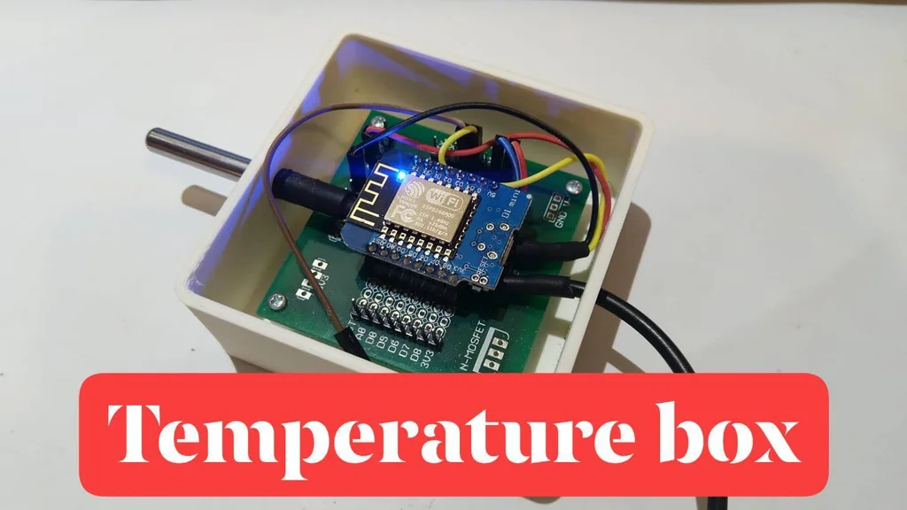
Simple DS18B20 based temperature sensor appliance with open source 3D printable box and prototype PCB.
The box and the prototype PCB is optional, only one ESP8266 based MCU is needed and one DS18B20 temperature sensor. I suggest to you a WEMOS D1 mini, but this example works with an ESP-01 as well.
This example does not explain how to write and upload an Arduino program to the ESP8266 MCU, so be aware of this skill before following me. 🙂
Supplies
ESP8266 MCU (recommended WEMOS D1 mini)
DS18B20
4.7 kΩ resistor
some wire
optionally prototype PCB for WEMOS D1 mini
optionally 3D printed box
Step 1
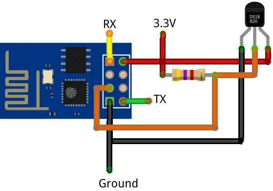
It’s easy as pie, check the wiring schematics on the picture:
In case of bare ESP8266 board, connect the RX and TX to your USB-serial device, in case of any board with integrated USB this is not necessary.
Connect the GND and VCC to the ESP8266 board and to the DS18B20 sensor.
Connect the resistor between the VCC and the data wire of the DS18B20 sensor.
Connect the data wire of the DS18B20 sensor to one GPIO of the MCU (for example GPIO 2).
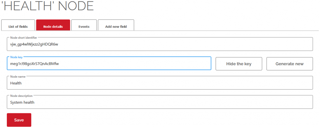
To connect with the cloud, you need to gather five identifier:
userShortId: the short identifier of you
deviceShortId: the short identifier of your device
deviceKey: the secret key of your device
nodeShortId: the short identifier of your device
fieldName: the name of the field
Step 4
Here is the example code, you need to replace the identifiers to your identifier, replace the SSID and the password to your WiFi credentials and check the GPIO number of the DS18B20 data wire.
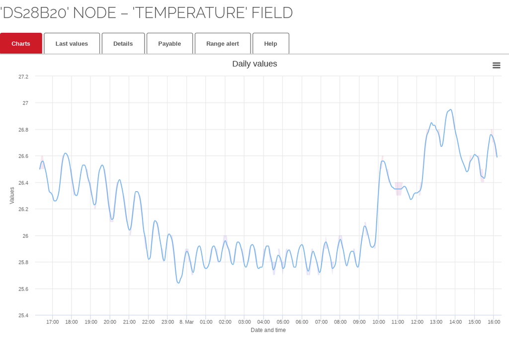
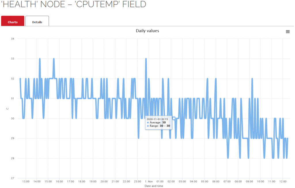
Upload the compiled firmware to your device. If everything is fine, your thermometer box will send the sensor measurements to the cloud and you’ll see such nice graphs over time if enough measurements have accumulated.
This CANBed-FD adopts MCP2517FD CAN Bus controller with SPI interface and MCP2542FD CAN transceiver to achieve the CAN-BUS capability. With an OBD-II converter cable added on and the OBD-II library imported, you are ready to build an onboard diagnostic device.
Compact size (56x41mm)
Work at CAN-FD and CAN 2.0
Industrial standard 9 pin sub-D connector or 4-pin terminal
OBD-II and CAN standard pinout selectable at sub-D connector
2 x 4-Pin Grove connectors compatible with the Grove ecosystem
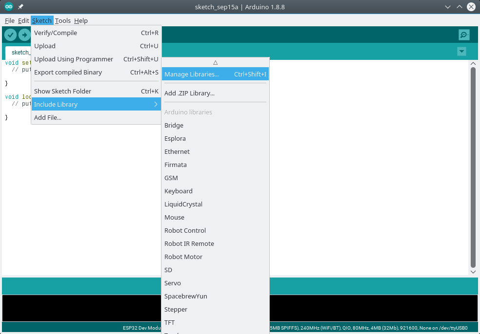
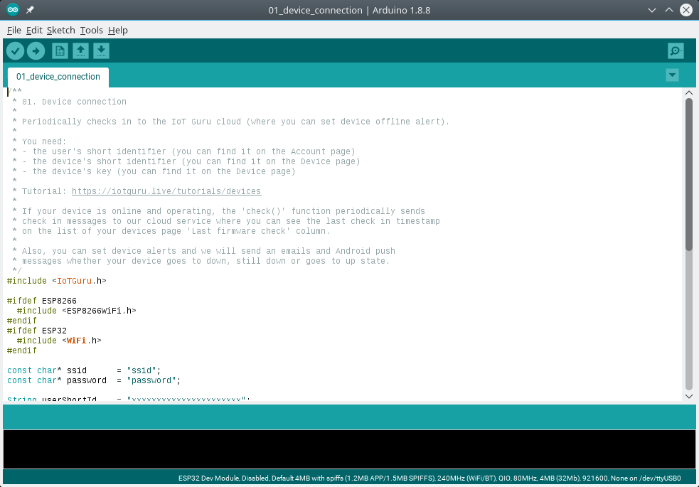
To install The IoT Guru integration into your Arduino IDE you can use the Library Manager (available from IDE version 1.6.2). Open the IDE and click to the Sketch menu and then Include Library > Manage Libraries.
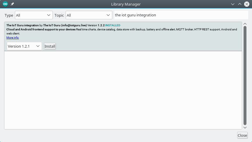
Step 2
Then the Library Manager will open and you will find a list of libraries that are already installed or ready for installation. In order to install The IoT Guru integration, search for “The IoT Guru integration“, scroll the list to find it and click on it.
Finally click on install and wait for the IDE to install The IoT Guru integration. Downloading may take time depending on your connection speed. Once it has finished, an Installed tag should appear next to the The IoT Guru integration library. You can close the Library Manager.
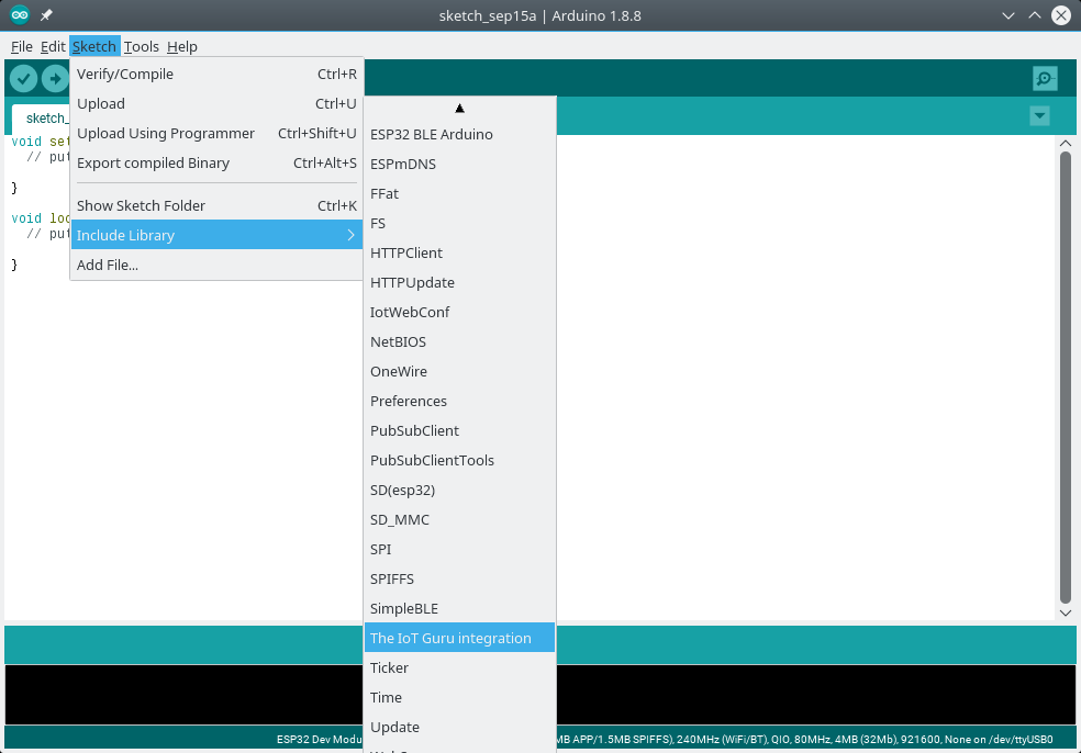
Step 3
You can now find The IoT Guru integration available in the Sketch > Include Library menu.
Step 4
We included some examples to our library, so that you can choose various examples to integrate your devices with our services, for example the basic device connection:
This high-quality camera is equipped with an IMX477 12.3MP high quality camera module which adopts the IMX477R sensor. It supports CS-mount lenses by default, but however, a C-CS adapter is included in order to use C mount lenses as well with this camera. It is compatible with Raspberry Pi Compute Module 3, 3 Lite, 3+, 3+ Lite, and NVIDIA Jetson Nano. This offers a higher resolution (12.3MP) and higher sensitivity (nearly 50% greater area per pixel for improved low-light performance) than the traditional 8MP IMX219 cameras.
Sony IMX477 sensor with 12.3MP for high resolution
Greater pixel area for improved low-light performance
Back-illuminated sensor architecture for improved sensitivity
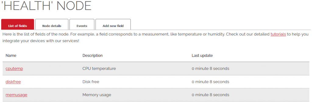
This tutorial will show you how to use IoT Guru Cloud to monitor the health of your Raspberry Pi and alert you when something is wrong.
At the end of this tutorial, you will run a Python script every five minutes using crontab to send your Raspberry Pi’s temperature, free disk space and memory usage to the cloud using our REST API.
Step 1
First of all, we suggest to read our basic tutorials about devices, nodes and fields:
We use cookies to ensure that we give you the best experience on our website. If you continue to use this site we will assume that you are happy with it.